- By school
- 0 Comment
- 01 Oct 2024
To determine the resistivity of two / three wires by plotting a graph for potential difference versus current | CBSE Class 12th Physics Practical
Experiment – 1
Objective:
To determine the resistivity of two wires by plotting a graph for potential difference versus current.
Required Apparatus:
Two resistance wires, a voltmeter (0-3)V and an ammeter (0-3 se) A of appropriate range, a battery/battery eliminator, a rheostat, a meter scale, a one-way key, connecting wires, and a screw gauge.
Formula Used:
By Ohm’s law
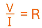
Where R is the constant of proportionality, it is known as the resistance of the conductor. R depends on the nature of the material, temperature and dimension of the conductor.
Specific resistance (ρ) of the material is given by

Where L is the length and D is the diameter of the given wire
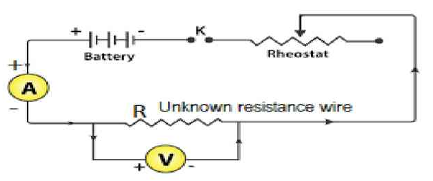
Circuit Diagram:
Observations:
- Range of ammeter = (0 – 3) A
- The least count of ammeter = 0.05 A
- Range of voltmeter = (0 -3) V
- The least count of voltmeter = 0.05 V
- The least count of metre-scale (L.C.) =0.1 cm
Zero error, e=0 mm, Zero correction, c = 0 mm
For 1st wire:
Length of the given wire, L= 15 cm = 0.15 m
Observation Table for Resistance
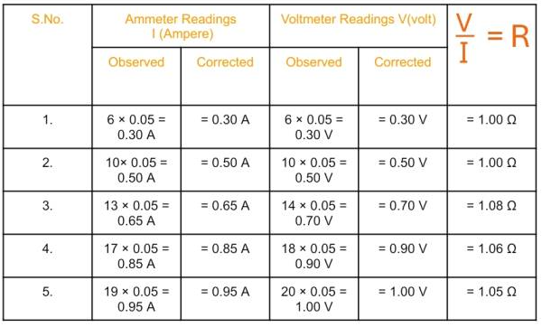
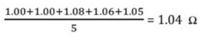
Mean value of resistance, R=
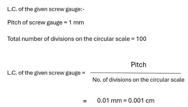
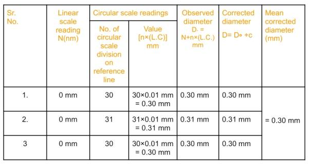
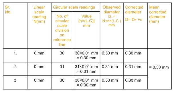
.Table for Diameter of wire:
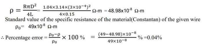
Calculation for Specific Resistance:
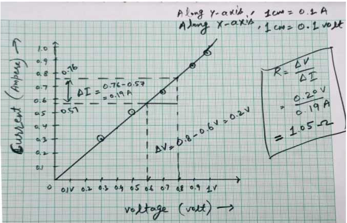
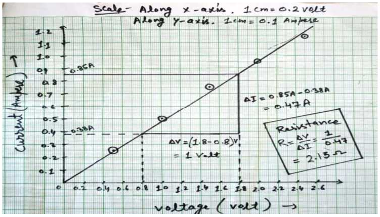
Graph – Potential difference versus Current
For 2nd wire:
Length of the given wire, L= 29cm = 0.29cm
Observation table for Resistance:

Table for Diameter of wire:
Calculation for Specific Resistance:

Graph – Potential difference versus Current:
Result:
- Resistance of first wire from table = 1.04 Ω and from graph 1.05 Ω
- Resistivity of 1st wire=48.98×10–⁸ Ω-m
- Percentage error = 0.04%.
- Resistance of 2nd wire from table = 2.06 Ω and from graph = 2.00 Ω
- Resistivity of 2nd wire = 50.19×10–⁸ Ω-m
- Percentage error = 2.43%.
Precautions:
- The connection should be neat clean and tight.
- Thick connections wire should be used for the connections.
- The voltmeter and ammeter should be of proper range.
- A low-resistance rehosteat should be used.
- The key should be inserted only while taking observation to avoid heating of resistance.
- At one place, the diameter of the wire should be measured in two mutually perpendicular directions.
- The wire should not make a loop.
Source of Error:
- The instrument crew may be lose.
- Thick connection wires may not be available.
- Rehosteat may have high resistance.
- The wire may not have uniform thickness.
- The screw gauge may have faults like a ‘back lash’ error and a wrong pitch.